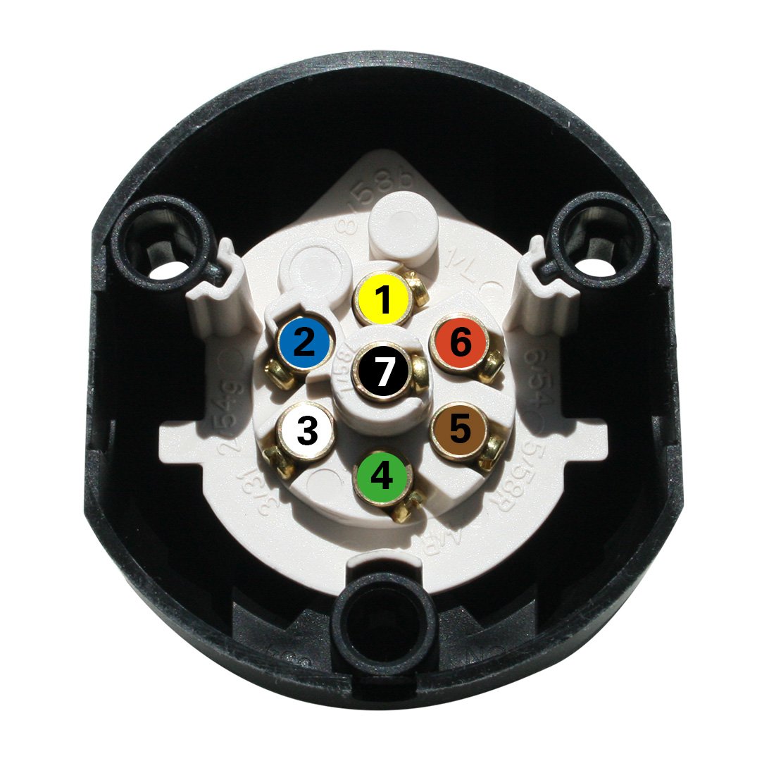
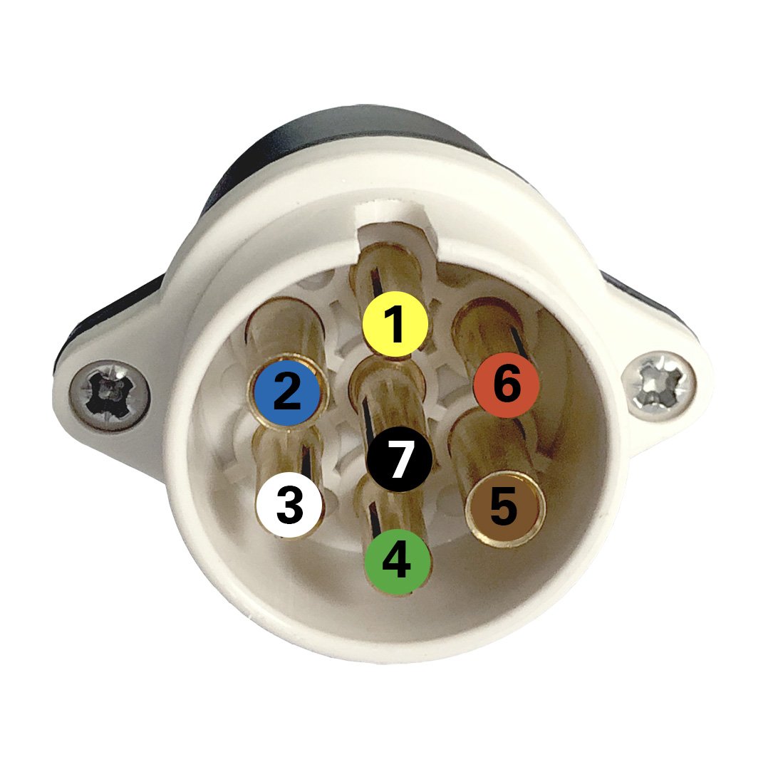
The standard ISO 3732 for trailer connectors was issued in 1982 as a supplement for the standard ISO 1724 from 2 years prior. The standards include a name affix to further define their area of application - ISO 3732 is Type S (supplemental) whereas ISO 1724 is Type N (normal). The purpose of the Type S connectors is to transfer signals and power for functionalities which cannot be served by the 7-pin Type N plugs and sockets (for example reversing light or steady plus for a caravan). The latest revision is from 2003. For a better recognizability, the housing of the supplementary system is white while the "normal" system features a black housing. Due to a different contact arrangement whithin the connectors, users can not accidentally plug a normal plug into a supplementary socket and vice versa.
Application of ISO 3732 Type S
When a trailer coupled to a passenger vehicle necessitates more than just the basic lighting functions, the connector system according to ISO 1724 is not sufficient as the 7 pins cannot accommodate any further functionalities. The plugs and sockets according to ISO 3732 add 7 more lines to transfer - for example - the steady plus for a caravan to supply consumers within the trailer (like a fridge).
The supplemental socket has been in use particularly in the UK. However, it is continually replaced by the 13-pin connector according to ISO 11446, which has been developed in the 1980s and which integrates the functionalities of the Type N and Type S 7-pin connector systems.
Scope of ISO 3732 Type S
The standard ISO 3732 specifies the dimensions of, and requirements for, 7-pole connectors of type 12 S and their contact allocation for the electrical connection of towing (passenger cars or light commercial vehicles) and towed vehicles with 12 V nominal supply voltage, thus ensuring interchangeability. A 12 S connector is intended to be used in addition to a 12 N connector according to ISO 1724 where more than 7 poles are required.

Contact Allocation for Connectors According to ISO 3732
| Contact no. | Function | Cross-sectional area | Core insulation color | Designation according to DIN 72552 |
|---|---|---|---|---|
| 1 | Reversing light | 1,5 mm² | yellow | RF or ZR |
| 2 | Reserved for future allocation | -- | blue | |
| 3 | Return for circuit for contact no. 4 | 2,5 mm² | white | 31 |
| 4 | Power supply (steady, constant) | 2,5 mm² | green | 30L |
| 5 | Not allocated | 1,5 mm² | brown | |
| 6 | Power supply controlled by ignition switch | 2,5 mm² | red | 15 |
| 7 | Return for circuit for contact no. 6 | 2,5 mm² | black | 31 |


